
CCS5.4+Proteus8的F28027實踐課十一、序列12864
阿新 • • 發佈:2019-01-27
週末出去玩了兩天,剛到家,昨天有個同學諮詢序列12864的東西,真不好意思,現在才以部落格的形式來解答。
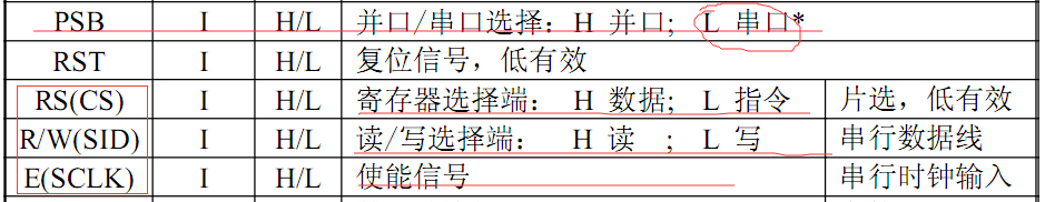
所謂12864的序列控制,只用到了三根線:CS、SID、SCLK,其中CS訊號用來選擇控制資料和指令的輸入,SID就是資料線,SCLK使能訊號線。
瞭解了幾個引腳,我們再來看下時序圖:
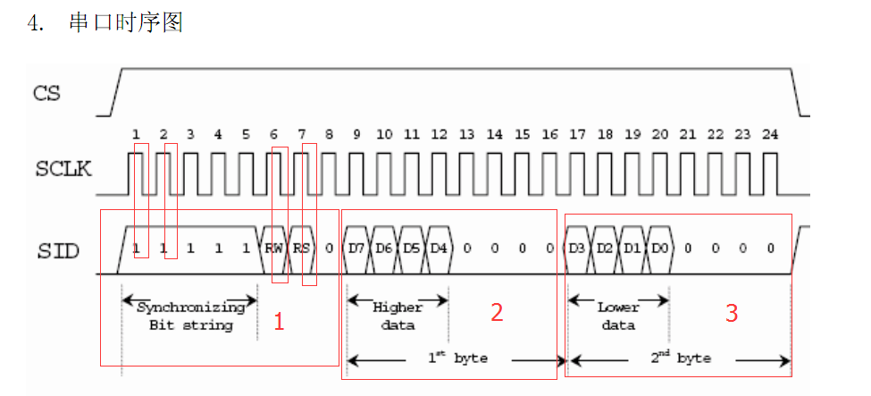
從時序圖可以看出來,每一次操作都要寫入三個位元組:控制位元組、高四位、低四位。其中寫指令的時候是0xf8+cmd&0xf0+(cmd<<4)&0xf0,寫資料是0xfa+data&0xf0+(data<<4)&0xf0。另外還有一點就是,資料是下降沿寫入,昨天那位同學應該是這裡出錯了。
好了,需要了解的理論知識就這麼多,我們現在開始寫程式。
先寫F2802x_LCD12864.h檔案
// auther: wangdingfa
// Checkin $Date: July 31, 2016 22:45:31 $
//###########################################################################
//
// FILE: F2802x_LCD12864.h
//
// TITLE: LCD12864 Initialization & Support Functions.
//
#ifndef F2802x_LCD12864_H
#define F2802x_LCD12864_H
#define CS GpioDataRegs.GPADAT.bit.GPIO16 再寫F2802x_LCD12864.c檔案
// auther: wangdingfa
// Checkin $Date: July 31, 2016   22:45:31 $
//###########################################################################
//
// FILE:    F2802x_LCD12864.c
//
// TITLE:    LCD12864 Initialization & Support Functions.
//

#include "F2802x_Device.h"     // Headerfile Include File
#include "F2802x_Examples.h"   // Examples Include File

void SendByte_LCD12864(unsigned char byte)
{
    char i;
    CS=1;
    for(i = 0;i < 8;i ++)
    {
        if((byte<<i) & 0x80)
        {
            SID = 1;
        }
        else
        {
            SID = 0;
        }
        DELAY_US(1);
        SCLK = 1;
        DELAY_US(1);
        SCLK = 0;
        DELAY_US(1);
    }
    DELAY_US(10);
}

//---------------------------------------------------------------------------
// WRITEDATA_LCD12864:
//---------------------------------------------------------------------------
// This function writes data to LCD12864
void WRITEDATA_LCD12864(unsigned char data)
{
    CS = 1; //開啟片選
    DELAY_US(10);
    SendByte_LCD12864(0xfa);//第一位元組
    DELAY_US(10);
    SendByte_LCD12864(data & 0xf0);  //第二位元組
    DELAY_US(10);
    SendByte_LCD12864((data << 4) & 0xf0);//第三位元組
    DELAY_US(10);
    CS = 0;
    DELAY_US(100);
}

//---------------------------------------------------------------------------
// WRITECMD_LCD12864:
//---------------------------------------------------------------------------
// This function writes cmd to LCD12864
void WRITECMD_LCD12864(unsigned char cmd)
{
    CS = 1;//開啟片選,高電平有效
    DELAY_US(10);
    SendByte_LCD12864(0xf8); //第一位元組
    DELAY_US(10);
    SendByte_LCD12864(cmd & 0xf0);     //第二位元組
    DELAY_US(10);
    SendByte_LCD12864((cmd << 4) & 0xf0);//第三位元組
    DELAY_US(10);
    CS = 0;
    DELAY_US(100);
}


//---------------------------------------------------------------------------
// InitLCD12864:
//---------------------------------------------------------------------------
// This function initializes the LCD12864 to a known (default) state.
// such as FUNCTION SET,DSIPLAY SET,CLEAR SCREEN

void InitLCD12864(void)
{
    DELAY_US(10000);
    WRITECMD_LCD12864(0x30);
    DELAY_US(1000);
    WRITECMD_LCD12864(0x30);
    DELAY_US(100);
    WRITECMD_LCD12864(0x0c);
    DELAY_US(1000);
    WRITECMD_LCD12864(0x01);
    DELAY_US(10000);
    WRITECMD_LCD12864(0x06);
    DELAY_US(10000);
}

//===========================================================================
// End of file.
//===========================================================================
最後還是主函式,這個主函式跟上次並行的一樣,都是測試語句而已
#include "DSP28x_Project.h"     // Device Headerfile and Examples Include File

void main(void)
{

// Step 1. Initialize System Control:
// PLL, WatchDog, enable Peripheral Clocks
// This example function is found in the DSP2802x_SysCtrl.c file.
   InitSysCtrl();

// Step 2. Initalize GPIO:
// This example function is found in the DSP2802x_Gpio.c file and
// illustrates how to set the GPIO to it's default state.
   InitGpio();

// Step 3. Clear all interrupts and initialize PIE vector table:
// Disable CPU interrupts
   DINT;

// Initialize PIE control registers to their default state.
// The default state is all PIE interrupts disabled and flags
// are cleared.
// This function is found in the DSP2802x_PieCtrl.c file.
   InitPieCtrl();

// Disable CPU interrupts and clear all CPU interrupt flags:
   IER = 0x0000;
   IFR = 0x0000;

// Initialize the PIE vector table with pointers to the shell Interrupt
// Service Routines (ISR).
// This will populate the entire table, even if the interrupt
// is not used in this example.  This is useful for debug purposes.
// The shell ISR routines are found in DSP2802x_DefaultIsr.c.
// This function is found in DSP2802x_PieVect.c.
   InitPieVectTable();


// Step 4. Initialize all the Device Peripherals:
// This function is found in DSP2802x_InitPeripherals.c
// InitPeripherals(); // Not required for this example

// Step 5. User specific code:

   InitLCD12864();

   WRITECMD_LCD12864(0x80);
   WRITEDATA_LCD12864('a');
   WRITEDATA_LCD12864('b');
   WRITEDATA_LCD12864('c');
   WRITECMD_LCD12864(0x90);
   WRITEDATA_LCD12864('1');
   WRITEDATA_LCD12864('2');
   WRITEDATA_LCD12864('3');
   WRITECMD_LCD12864(0x88);
   WRITEDATA_LCD12864('x');
   WRITEDATA_LCD12864('y');
   WRITEDATA_LCD12864('z');
   WRITECMD_LCD12864(0x98);
   WRITEDATA_LCD12864('7');
   WRITEDATA_LCD12864('8');
   WRITEDATA_LCD12864('9');

   while(1)
   {
//     GpioDataRegs.GPATOGGLE.all=0x000000ff;
//       DELAY_US(1000);
   }
}
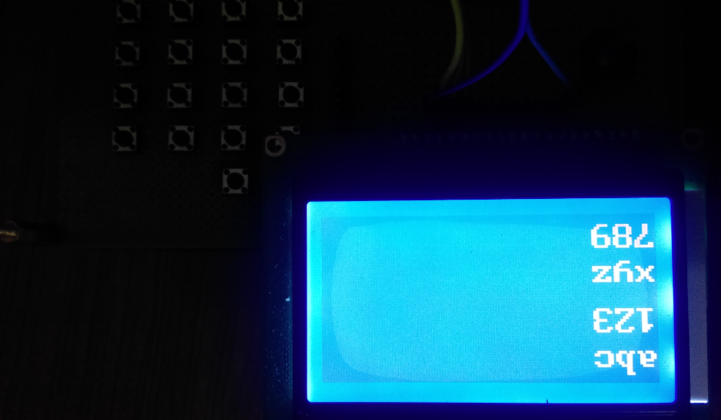
下載測試,結果正確,那說明昨天那位同學出錯的地方就是資料寫入跳變沿選擇錯了,應該是下降沿有效,而不是上升沿。
洗洗睡了,昨晚喝酒喝太多了,現在頭還有點暈暈的,老了,恢復的比較慢。
F28027菜鳥交流qq群107691092