
相機標定之OpenCV&Matlab
Camera Calibration
1.OpenCV Camera Calibration
OpenCV提供具體的標定策略和說明文件,可以直接使用,說明文件的位置"D:\opencv\sources\doc\tutorials\calib3d\camera_calibration";
例程的位置“D:\opencv\sources\samples\cpp\camera_calibration.cpp”
如何使用例程呢?首先修改配置文件xml
大概修改上述標註的幾個位置,然後執行camera_calibration.cpp即可;<?xml version="1.0"?> <opencv_storage> <Settings> <!-- 標定板的寬高各有多少角點Number of inner corners per a item row and column. (square, circle) --> <BoardSize_Width>7</BoardSize_Width> <BoardSize_Height>7</BoardSize_Height> <!--標定板上的方塊邊長,以毫米為單位 The size of a square in some user defined metric system (pixel, millimeter)--> <Square_Size>50</Square_Size> <!-- 選擇標定模式The type of input used for camera calibration. One of: CHESSBOARD CIRCLES_GRID ASYMMETRIC_CIRCLES_GRID --> <Calibrate_Pattern>"CHESSBOARD"</Calibrate_Pattern> <!-- The input to use for calibration. 所採集的標定影象儲存的路徑及名稱xml檔 To use an input camera -> give the ID of the camera, like "1" To use an input video -> give the path of the input video, like "/tmp/x.avi" To use an image list -> give the path to the XML or YAML file containing the list of the images, like "/tmp/circles_list.xml" --> <Input>"./vtDirTest.xml"</Input> <!-- If true (non-zero) we flip the input images around the horizontal axis.--> <Input_FlipAroundHorizontalAxis>0</Input_FlipAroundHorizontalAxis> <!-- Time delay between frames in case of camera. --> <Input_Delay>100</Input_Delay> <!-- How many frames to use, for calibration. --> <Calibrate_NrOfFrameToUse>25</Calibrate_NrOfFrameToUse> <!-- Consider only fy as a free parameter, the ratio fx/fy stays the same as in the input cameraMatrix. Use or not setting. 0 - False Non-Zero - True--> <Calibrate_FixAspectRatio> 1 </Calibrate_FixAspectRatio> <!-- If true (non-zero) tangential distortion coefficients are set to zeros and stay zero.--> <Calibrate_AssumeZeroTangentialDistortion>1</Calibrate_AssumeZeroTangentialDistortion> <!-- If true (non-zero) the principal point is not changed during the global optimization.--> <Calibrate_FixPrincipalPointAtTheCenter> 1 </Calibrate_FixPrincipalPointAtTheCenter> <!-- 輸出標定後的內參/外參以及其他引數的文件名稱路徑The name of the output log file. --> <Write_outputFileName>"out_camera_vt.xml"</Write_outputFileName> <!-- If true (non-zero) we write to the output file the feature points.--> <Write_DetectedFeaturePoints>1</Write_DetectedFeaturePoints> <!-- If true (non-zero) we write to the output file the extrinsic camera parameters.--> <Write_extrinsicParameters>1</Write_extrinsicParameters> <!-- If true (non-zero) we show after calibration the undistorted images.--> <Show_UndistortedImage>1</Show_UndistortedImage> </Settings> </opencv_storage>
因為據說使用Matlab的工具箱進行標定會比較準確,所以計劃對比測試兩種標定方式;
2.Matlab Calibration
首先下載toolbox_calib.zip,在【3】中有下載連結;解壓之後放在工作目錄下,同時跟隨【4】進行標定,敘述很詳盡;
但因為內容較多,現簡略敘述:
2.1 啟動標定工具箱
執行calib.m,選擇影象載入模式

當影象量大且多時需要使用第二種方式;此處選擇標準模式為例:

2.2 載入影象
進入影象所在目錄,然後點選Image names按鈕

首先輸入標定影象序列的名稱字首(不包含數字序號)如上方式,然後選擇格式;ok;

2.3 提取角點
點選Extract grid corners按鈕,在命令視窗如下述

直接回車,將選擇預設模式;視窗的大小為11×11,然後在對每一幅測試圖檔進行手動設定最外圍的四個角點
按逆時針順序進行選擇
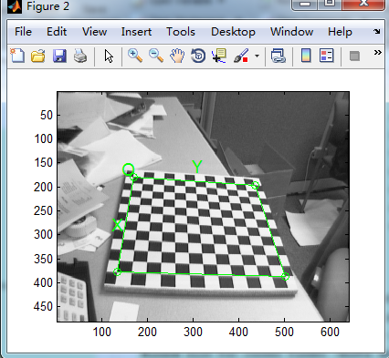
此時需要設定每個小方格在現實世界中的寬高,以便隨後角點的自動選擇;
此處設定為30mm×30mm;只需第一次設定;


然後每一幅影象都需要設定外圍的四個角點,這樣會不會手痠???
若已經做過一次,可點選load選項,會自動載入Calib_Results.mat中的角點資訊;
2.4 標定
在所有的圖檔都已經角點提取完畢之後,點選Calibration進行標定;

說明
A. 通過Recomp. corners按鈕提高標定精確度;
B. Analyse error展示角點誤差分佈,用滑鼠左鍵點選後,在命令視窗可直接顯示該點資訊;

C.Add/Suppress images 去除不需要的圖檔;
D. Show Extrinsic模擬每幅影象採集時的相對相機的位置角度;

其他的慢慢探索,文件【3】【4】相當詳細;
為便於後續查詢,也上傳一份toobox及圖檔;下載地址