STM32的RFID射頻讀寫控制裝置
阿新 • • 發佈:2017-05-07
please include .cn mage str rfid alt all float
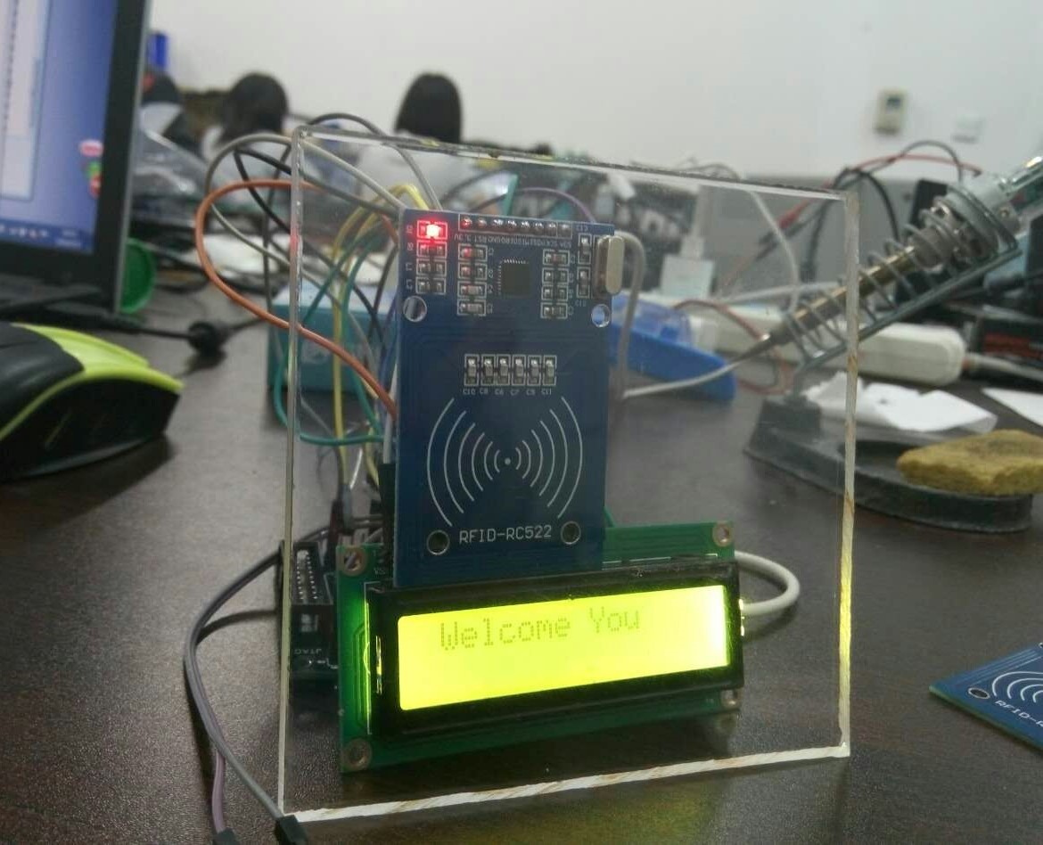
,大二上學期做的,過了很久,先上一下圖:

這並不是做個最後一版;主體是RC552+STM32+1062;蜂鳴器,繼電器,LED等;反正最後的效果就是,刷一下卡,1602顯示一下持卡人(需要提前註冊,註冊方法也就是在數組裏多添加幾個編號,哈哈,畢竟沒有數據庫暫時也只能想到這樣了);然後蜂鳴器響,燈亮,繼電器開;
貼一下關鍵代碼:
#include "delay.h" #include "sys.h" #include "usart.h" #include "led.h" #include "lcd1602.h" #include "key.h" #include <stdio.h> #include"stm32f10x_gpio.h" #include "stm32f10x_rcc.h" #include "main.h" #include "mfrc522.h" #include "stm32f10x.h" #include "exti.h" USART_InitTypeDef USART_InitStructure; void GPIO_ini() { GPIO_InitTypeDef GPIO_InitStructure; /* Enable the GPIO Clock */ RCC_APB2PeriphClockCmd(MF522_RST_CLK, ENABLE);/* Configure the GPIO pin */ GPIO_InitStructure.GPIO_Pin = MF522_RST_PIN; GPIO_InitStructure.GPIO_Mode = GPIO_Mode_Out_PP; GPIO_InitStructure.GPIO_Speed = GPIO_Speed_2MHz; GPIO_Init(MF522_RST_PORT, &GPIO_InitStructure); /* Enable the GPIO Clock */ RCC_APB2PeriphClockCmd(MF522_MISO_CLK, ENABLE);/* Configure the GPIO pin */ GPIO_InitStructure.GPIO_Pin = MF522_MISO_PIN; GPIO_InitStructure.GPIO_Mode = GPIO_Mode_IN_FLOATING; GPIO_InitStructure.GPIO_Speed = GPIO_Speed_2MHz; GPIO_Init(MF522_MISO_PORT, &GPIO_InitStructure); /* Enable the GPIO Clock */ RCC_APB2PeriphClockCmd(MF522_MOSI_CLK, ENABLE); /* Configure the GPIO pin */ GPIO_InitStructure.GPIO_Pin = MF522_MOSI_PIN; GPIO_InitStructure.GPIO_Mode = GPIO_Mode_Out_PP; GPIO_InitStructure.GPIO_Speed = GPIO_Speed_2MHz; GPIO_Init(MF522_MOSI_PORT, &GPIO_InitStructure); /* Enable the GPIO Clock */ RCC_APB2PeriphClockCmd(MF522_SCK_CLK, ENABLE); /* Configure the GPIO pin */ GPIO_InitStructure.GPIO_Pin = MF522_SCK_PIN; GPIO_InitStructure.GPIO_Mode = GPIO_Mode_Out_PP; GPIO_InitStructure.GPIO_Speed = GPIO_Speed_2MHz; GPIO_Init(MF522_SCK_PORT, &GPIO_InitStructure); /* Enable the GPIO Clock */ RCC_APB2PeriphClockCmd(MF522_NSS_CLK, ENABLE); /* Configure the GPIO pin */ GPIO_InitStructure.GPIO_Pin = MF522_NSS_PIN; GPIO_InitStructure.GPIO_Mode = GPIO_Mode_Out_PP; GPIO_InitStructure.GPIO_Speed = GPIO_Speed_2MHz; GPIO_Init(MF522_NSS_PORT, &GPIO_InitStructure); /* Enable the GPIO Clock */ RCC_APB2PeriphClockCmd(LED_CLK, ENABLE); /* Configure the GPIO pin */ GPIO_InitStructure.GPIO_Pin = LED_PIN; GPIO_InitStructure.GPIO_Mode = GPIO_Mode_Out_PP; GPIO_InitStructure.GPIO_Speed = GPIO_Speed_2MHz; GPIO_Init(LED_PORT, &GPIO_InitStructure); } void InitializeSystem() { //LED_OFF; delay_10ms(10); PcdReset(); PcdAntennaOff(); PcdAntennaOn(); M500PcdConfigISOType( ‘A‘ ); //LED_ON; delay_10ms(10); //LED_OFF; delay_10ms(10); //LED_ON; delay_10ms(10); //LED_OFF; } int main(void) { char status; unsigned char snr, buf[16], TagType[2], SelectedSnr[4], DefaultKey[6] = {0xFF, 0xFF, 0xFF, 0xFF, 0xFF, 0xFF}; u8 t; u8 str[] = "Jiaomengke"; u8 str2[] = "Jiaomengke2"; u8 str3[] = "Jiaomengke"; delay_init(); NVIC_Configuration(); uart_init(9600); GPIO_Configuration(); KEY_Init(); LED_Init(); flog: LCD1602_Init(); //LCD1602_Show_Str(0, 0, "Please put card"); LCD1602_Show_Str(1, 0, " Please"); LCD1602_Show_Str(2, 1, " put card"); GPIO_ini(); InitializeSystem( ); while(1) { status= PcdRequest(REQ_ALL,TagType); if(!status) { status = PcdAnticoll(SelectedSnr); if(!status) { status=PcdSelect(SelectedSnr); if(!status) { snr = 0; status = PcdAuthState(KEYA, (snr*4+3), DefaultKey, SelectedSnr);// D£?é0éè???ü?? { if(!status) { status = PcdRead((snr*4+1), buf); //PcdWrite((snr*4+1), buf); // ?áè?0éè??1?éêy?Y if(!status && (SelectedSnr[2]==0x3e||SelectedSnr[2]==0xf6||SelectedSnr[2]==0xf4||SelectedSnr[2]==0xe7)) { LED_ON; WaitCardOff(); while(1) { LCD1602_ClearScreen(); LCD1602_Show_Str(1, 0, " Welcome You"); if(SelectedSnr[2]==0x3e) LCD1602_Show_Str(2, 1, str); if(SelectedSnr[2]==0xf6) LCD1602_Show_Str(2, 1, str1); if(SelectedSnr[2]==0xf4) LCD1602_Show_Str(2, 1, str2); if(SelectedSnr[2]==0xe7) LCD1602_Show_Str(2, 1, str3); delay_ms(1000); LED_OFF; delay_ms(1000); goto flog; } } } } } } } LED_OFF; } }
STM32的RFID射頻讀寫控制裝置
